Should curved track be ground differently from tangent track?
Should curved track be ground differently from tangent track?
Yes, but not because a curve needs more passes. On tangent track one target profile and one depth figure fit both rails. On a curve the two rails carry two different contact problems and give up metal in different places, so the plan has to change in three things only: which shape each rail is ground to, how the depth budget is split across the head, and how soon the section comes back. The arithmetic underneath does not change — depth still comes from measured deviation, and total removal still stays inside the same envelope.
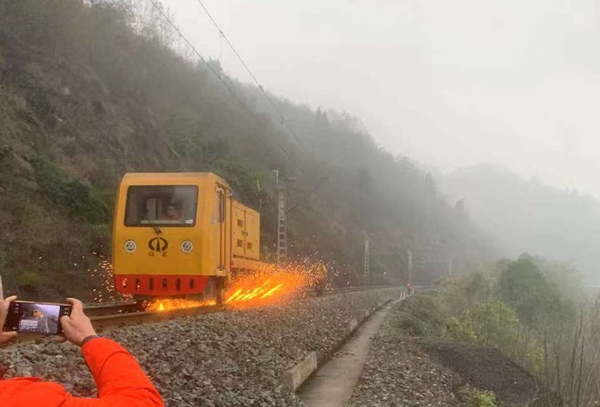
What changes from a tangent plan, and what does not
| Item | Tangent track | Curved track | What happens if you reuse the tangent plan |
|---|---|---|---|
| Target shape | One profile applied to both rails; the contact band sits near the crown by itself | Two targets: the high rail needs the gauge corner relieved so the band climbs back toward the crown, the low rail needs a crown that stays wide and central | The high rail is ground smooth on the gauge face while the wheel keeps running on it, so side wear returns at close to the previous rate |
| Where the metal comes off | Close to symmetrical across the head | Deliberately unequal: on the high rail of an R=800 m curve, six passes at 12 km/h took up to 0.3 mm on the field side but up to 1.8 mm on the gauge side — a six-fold spread inside a single pass plan | One average depth per rail over-grinds the side that was already close and leaves the gauge corner still proud |
| How often it returns | The long clock: about 100 Mt on plain line and large radius above 1,200 m | The short clock: 30-50 Mt on small-radius curves; in UK practice curves are planned near 15 Mt against about 45 Mt on straight track | The curve arrives at the next inspection already outside the band, and the correction then costs section instead of preventing it |
| Defect mix to read first | Corrugation, squatting, rail-head fatigue spread across the head | High rail: side wear and gauge-corner fatigue. Low rail: corrugation and surface cracking | You plan for the defect you can see from the cab instead of the one that decides the profile |
The tonnage numbers above are conditional ranges, not a schedule: the transferable part of the UK comparison is the ratio of roughly three to one between curve and straight, which is what a plan should carry over to another network — not the absolute tonnage. How the interval itself is calculated from a removal rate is set out in how a grinding interval is set by tonnage.
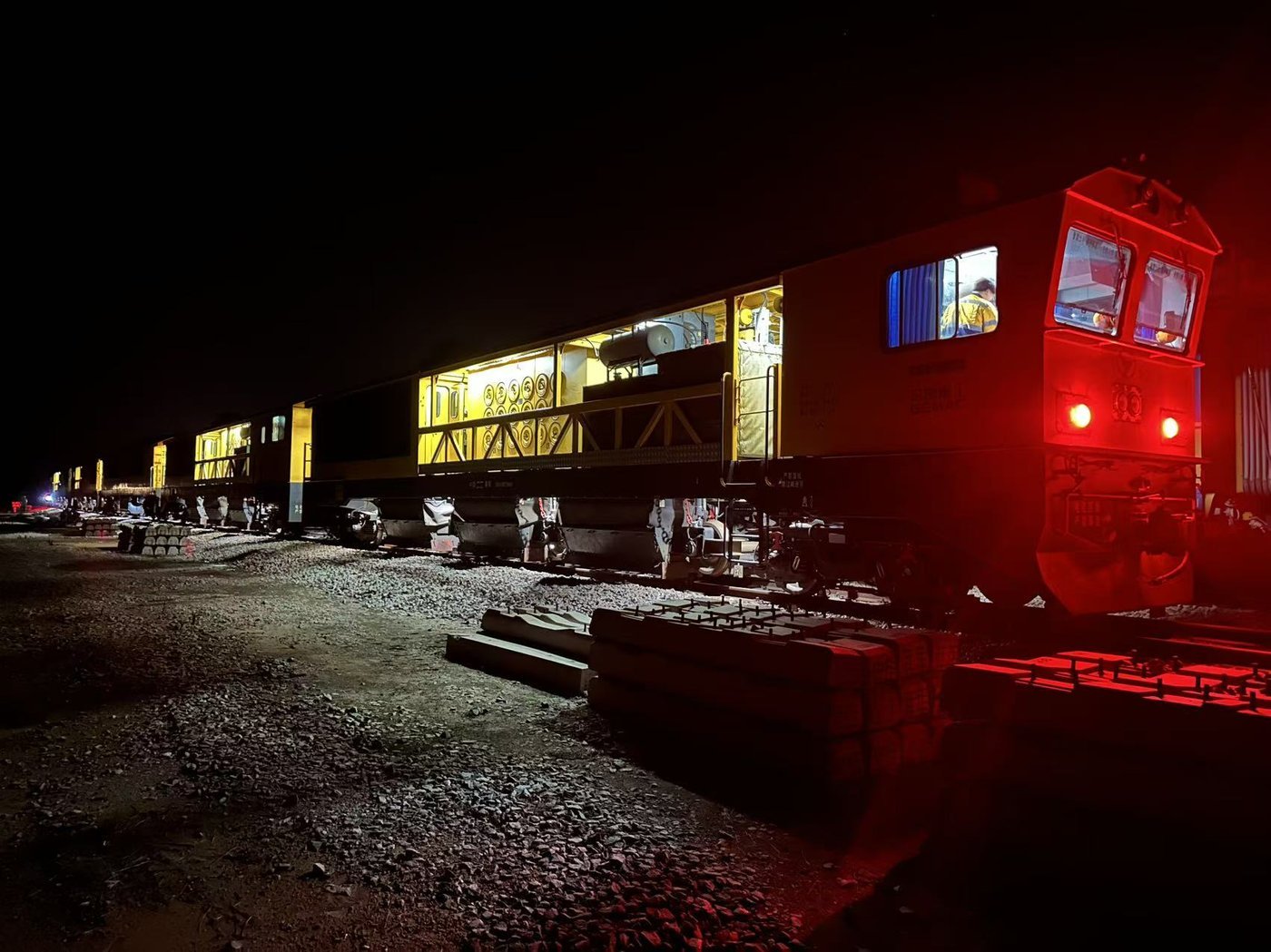
High rail and low rail are two different jobs
| Rail | What it loses | The grinding objective | What to check afterwards | How a wrong plan looks |
|---|---|---|---|---|
| High (outer) rail | Metal from the gauge face and gauge corner, plus rolling-contact fatigue at the corner | Profile recovery: move the contact band up and off the gauge face, and take the cracked layer with it | Head width, gauge-face angle, and where the running band actually sits relative to the crown — not just how bright the surface is | The gauge face looks clean and even polished, yet the band is still low and side wear continues |
| Low (inner) rail | Corrugation amplitude, surface cracking, light plastic flow on the crown | Amplitude removal: cut the peaks below the valleys instead of lowering the whole surface by one depth | The residual amplitude measured on the same chord at the same position, before and after | The surface looks freshly ground and the corrugation is back within a season, because the peak-to-peak distance was never reduced (see why grinding can make corrugation worse) |
This is also where curve work splits between machine types. A long machine works along the length and applies one angle set to every head; on the short transitions for a small radius, or where the high rail's gauge corner needs a shape the main head cannot reach, part of the job belongs to a smaller unit. That division is covered in large-machine and small-machine grinding, and the geometry of which angle covers which band of the head is in how a pass pattern and angle sequence are set.
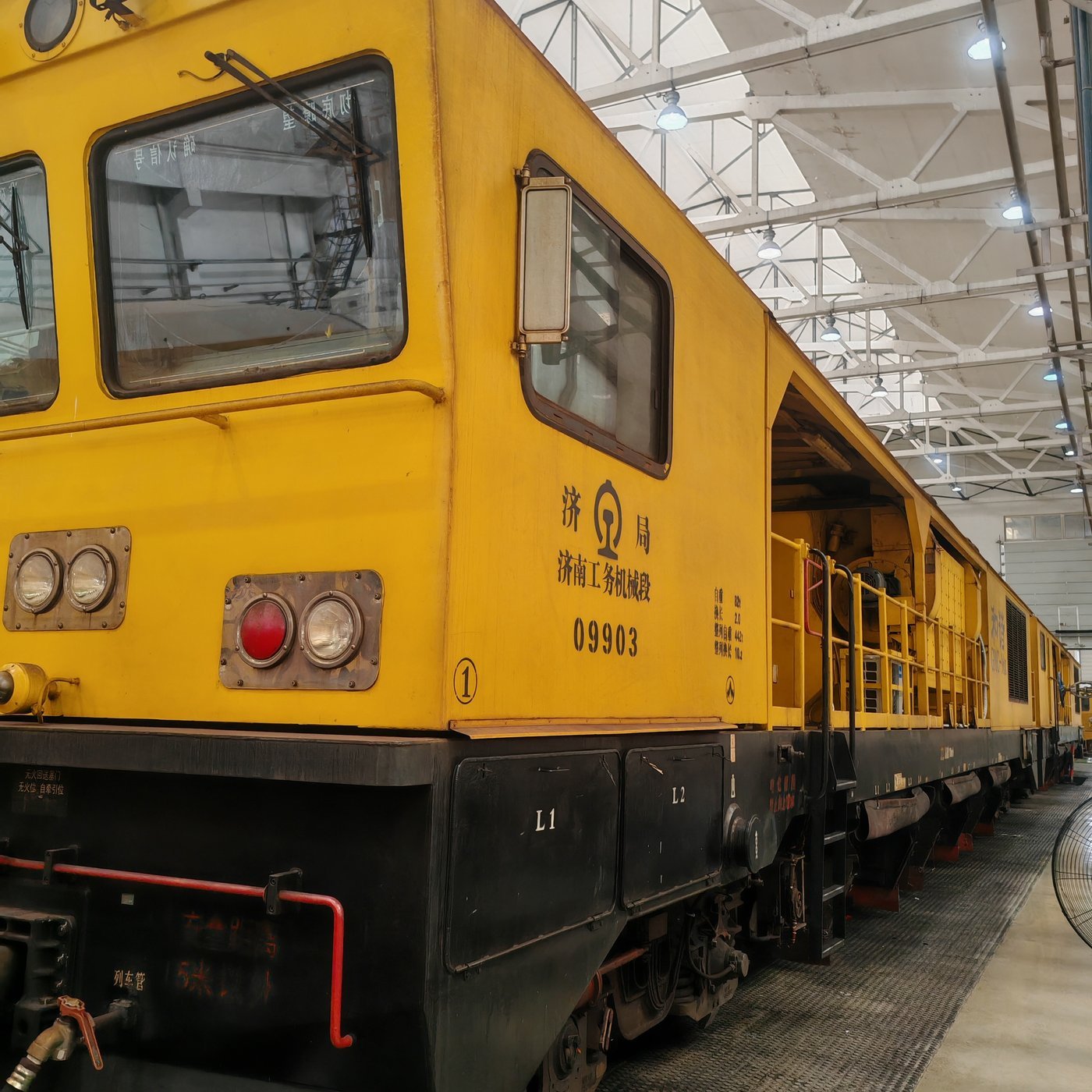
Uneven removal is normal — check these instead
| What the report shows | Normal or a fault | How to verify it | What to change |
|---|---|---|---|
| Gauge side lost several times the metal of the field side | Normal on any curve carrying side wear — the wear was there before the machine arrived | Per-position measurement on that rail, not a fleet or section average | Nothing, provided the total stays inside the envelope and the contact band has moved up |
| One rail inside tolerance, the other still outside | Normal; the two rails started from different shapes | Two separate tolerance reports, one per rail | Plan and accept the two rails separately from the start |
| Whole curve still short of target after the planned passes | A fault | Compare the removal actually achieved per pass with the figure the pass count was computed from | Passes were calculated from a tangent-line removal figure; recompute from measured removal at that speed on that curve |
| Gauge corner shiny again within weeks | A fault, and not a grinding-quality fault | Measure where the running band sits relative to the crown | The plan changed the surface but not the contact position — go back to the target profile drawing, covered in what the target rail profile is and who defines it |
Two numbers stay shared with tangent work and are the reason a curve job is not a licence to cut deeper. Planned depth runs from 0.1 mm upward for preventive work and 0.2 mm upward for corrective work, with total removal on the parent metal capped at 0.5 mm, and the working window for surface cracks is about 0.2 mm deep — the same figures as on plain line, detailed in safe grinding depth. What a Molaton wheel has to deliver for a curve plan is narrower than it sounds: the same removal per pass on the gauge side, where the contact arc is longest, from the first metre to the last. A wheel that fades there forces the operator to add passes or pressure, and both of those spend section the curve does not have.
Where a curve also carries corrugation, the set of defects becomes a combination rather than one item, and the treatment order changes; that case, including the specification side of it, is handled in managing side wear on curved track and in wheel selection for small-radius curve corrugation, which belongs to the consumable question rather than the strategy one.
Related questions you may also ask
What is the target rail profile and who defines it? How is a grinding pass pattern set, and why does the angle sequence matter? How is a rail grinding interval set by tonnage? Why does grinding sometimes make corrugation worse? What grinding depth is safe before you over-grind a rail? More answers on rail grinding strategy and equipmentDoes your curve plan treat both rails as one job?
Send RailwayCare the curve radius, the two rails' measured profiles and the last pass plan. We will tell you which rail is being averaged into the other, where the depth budget is being spent, and what a Molaton wheel schedule that holds removal on the gauge side would look like for that section.
Review My Curve Plan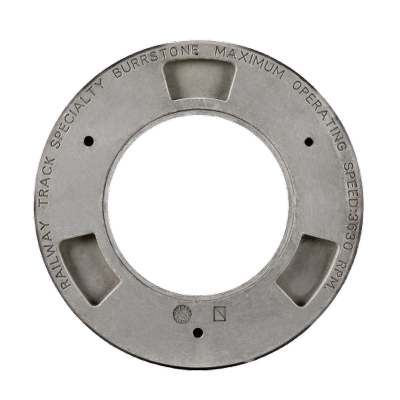

Are you looking for a reliable manufacturer of railway grinding and track maintenance equipment?
We can quickly provide customers with market analysis, technical support and customized services.
Safe Tracks Proven by China
- Name
- Phone
- *Title
- *Content