Aluminothermic Welding Explained: Process, Consumables, QC
Aluminothermic welding joins two rail ends by pouring superheated steel into a mould around them. The steel comes from a reaction between iron oxide and aluminium inside a disposable crucible, and the whole sequence — cut, align, seal, preheat, pour, cool, grind — takes a trained two-person crew about fifteen to twenty minutes at the trackside.
That simplicity is deceptive. The process has almost no adjustable parameters during the pour, so everything that determines whether the weld survives ten years of traffic has to be controlled before the crucible is lit: how the ends were cut, what the gap measures, whether the mould sealed, what the preheat reached, and how long the weld was left to cool.
Direct answer
This guide covers the process itself and the controls that make it repeatable. It is the first of three. The second covers the documentation and inspection regime that has to surround a welding procedure, and the third covers when this process is the right choice at all against flash butt welding.
If you already run aluminothermic welding and the question is why joints are failing, the answer is usually in one of five places — and four of them are preheat, gap, mould sealing and cooling discipline, not the consumable. Those are set out below.
Aluminothermic, Alumino Thermic and Thermite: Same Process
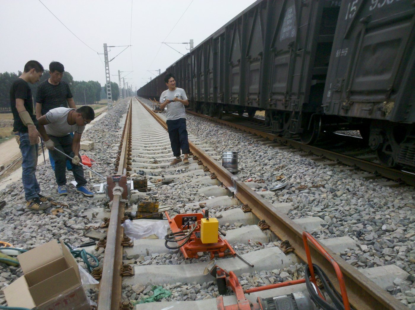
The search results for this process are split across three spellings, and buyers often assume they refer to different things. They do not.
Aluminothermic welding is the term used in the European standards — EN 14730-1 for process approval, EN 14730-2 for welder and contractor qualification. Alumino thermic welding, written as two words, is the same process and appears widely in supplier catalogues and tender documents, particularly outside Europe. Thermite welding is the trade name that became generic, from the German Thermit process, and remains the everyday term on North American and Australian track.
For the short definition used in rail replacement work, see what aluminothermic welding is.
All three describe a process in which iron oxide and aluminium react exothermically to produce steel at around 2,000 to 2,200 °C, which is cast into a mould around two preheated rail ends. Where the terms differ is only in who tends to use them: standards bodies say aluminothermic, procurement documents often say alumino thermic, and track gangs say thermite.
One genuine distinction is worth keeping. A small number of processes use a different exothermic chemistry or a different mould arrangement — enclosed or puddle arc welding, for example, deposits filler metal with an arc rather than casting it. Those are not aluminothermic welds and do not meet EN 14730. If a specification names aluminothermic welding, an arc-based alternative is not an equivalent substitute.
What Aluminothermic Welding Actually Does
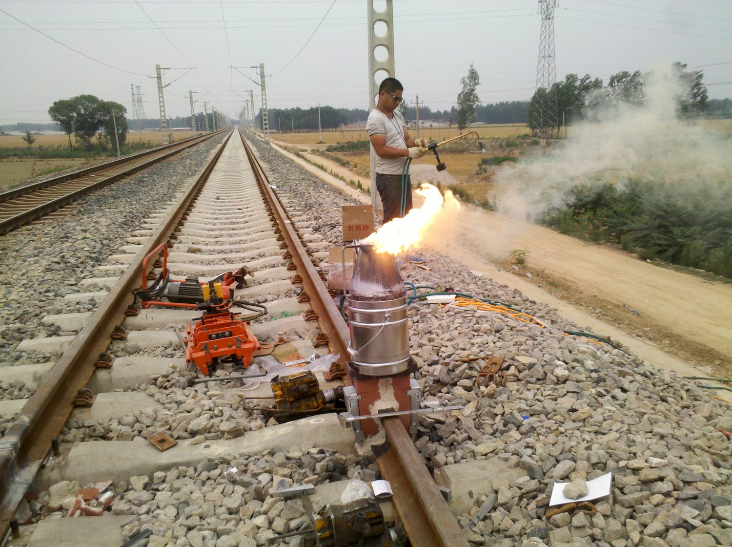
The reaction is straightforward chemistry. A charge of iron oxide and aluminium powder, with alloying additions, is ignited in a crucible above the joint. Aluminium has a higher affinity for oxygen than iron does, so it takes the oxygen, releasing enough heat to produce liquid steel at around 2,000 to 2,200 °C. The steel runs down into a sand mould that has been sealed around the two rail ends, fuses them, and solidifies.
Three things make this process unusual among welding methods.
It is a casting process, not a fusion-welding process. The rail ends do not melt and merge under an arc. They are heated and then surrounded by cast steel that bonds to them. That is why the preheat matters so much: it controls how much of the rail end participates in the bond, and how fast the cast steel cools against it.
There is nothing to adjust once the reaction starts. An arc welder can correct travel speed mid-pass. An aluminothermic welder cannot change anything after ignition. All the control is front-loaded into preparation, which is why the checkpoints in a proper procedure are almost all before the pour.
The consumable is specific to the rail profile and section. A charge sized for a 60E1 rail will not produce a sound weld on a different section, and the mould is profile-specific. This is also why an unlabelled or mismatched kit is a defect waiting to happen, and why traceability of the charge batch is a requirement in every serious standard.
Table 1 lists what a complete kit contains, and what each item's failure does to the weld.
| Kit item | Function | Failure mode if wrong or degraded |
|---|---|---|
| Crucible with lining | Holds the charge and contains the reaction | Moisture in the lining causes a violent reaction or gas porosity in the weld |
| One-shot charge (iron oxide + aluminium + alloys) | Produces the steel | Wrong grade gives wrong hardness and strength; damp charge gives porosity |
| Sand mould, profile-specific | Forms the cavity around the joint | Wrong profile gives an oversized or undersized collar and poor fusion at the web |
| Luting sand or sealing paste | Seals the mould joints | Any leak lets steel escape, producing a cold shut and an incomplete weld |
| Ignition device | Starts the reaction | Misfire wastes the charge; a partial ignition leaves unmelted material |
| Preheat burner, hoses, flashback arrestors | Brings the rail ends to temperature | Uneven preheat is the single most common cause of poor fusion |
| Alignment equipment: straight edge, gap gauge, clamps | Sets gap and straightness | Wrong gap changes the thermal mass and the collar geometry |
| Thermometer (contact or magnetic) | Verifies preheat | No verification means preheat is assumed rather than known |
The quality of the consumable matters, but it is not where most failures originate. In practice, a well-made kit used with poor preheat or a leaking mould produces a worse weld than an average kit used correctly. That ordering is worth remembering during a failure investigation, because the instinct is to blame the charge batch first.
The Rail Welding Procedure, Step by Step
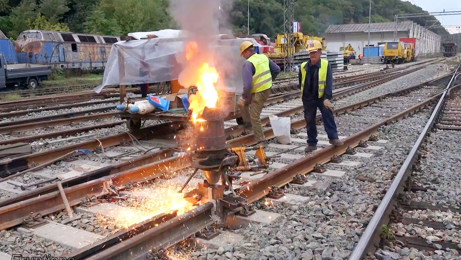
The sequence below is the standard trackside process. Timings and temperatures vary slightly between systems and between standards; the checkpoints do not.
1. Cut the rail ends square. A saw cut, not a flame cut: thermal cutting leaves a hardened and oxidised layer that will not fuse reliably. Both ends must be square within the tolerance your procedure specifies, because the gap and the collar geometry are set from these faces.
2. Clean the rail ends and the running surface. Rust, mill scale, grease and moisture all create inclusions. Cleaning is cheap and its omission is one of the most common causes of slag entrapment at the head.
3. Align the rails and set the gap. A straight edge over a one-metre span is the usual check. The gap is profile-dependent, and the tolerance is tight — EN 14730-1 works to ±2 mm on the welding gap, and the mould position must be within ±2 mm longitudinally. Too large a gap means more steel to feed and a larger heat-affected zone; too small a gap means incomplete fusion at the web.
4. Fit and seal the mould. The three-part sand mould is clamped around the joint, and every flange surface is sealed with luting sand or paste. This is the step where shortcuts are most expensive: a leak of a few millimetres allows liquid steel to escape and produces an incomplete weld that may pass a visual check.
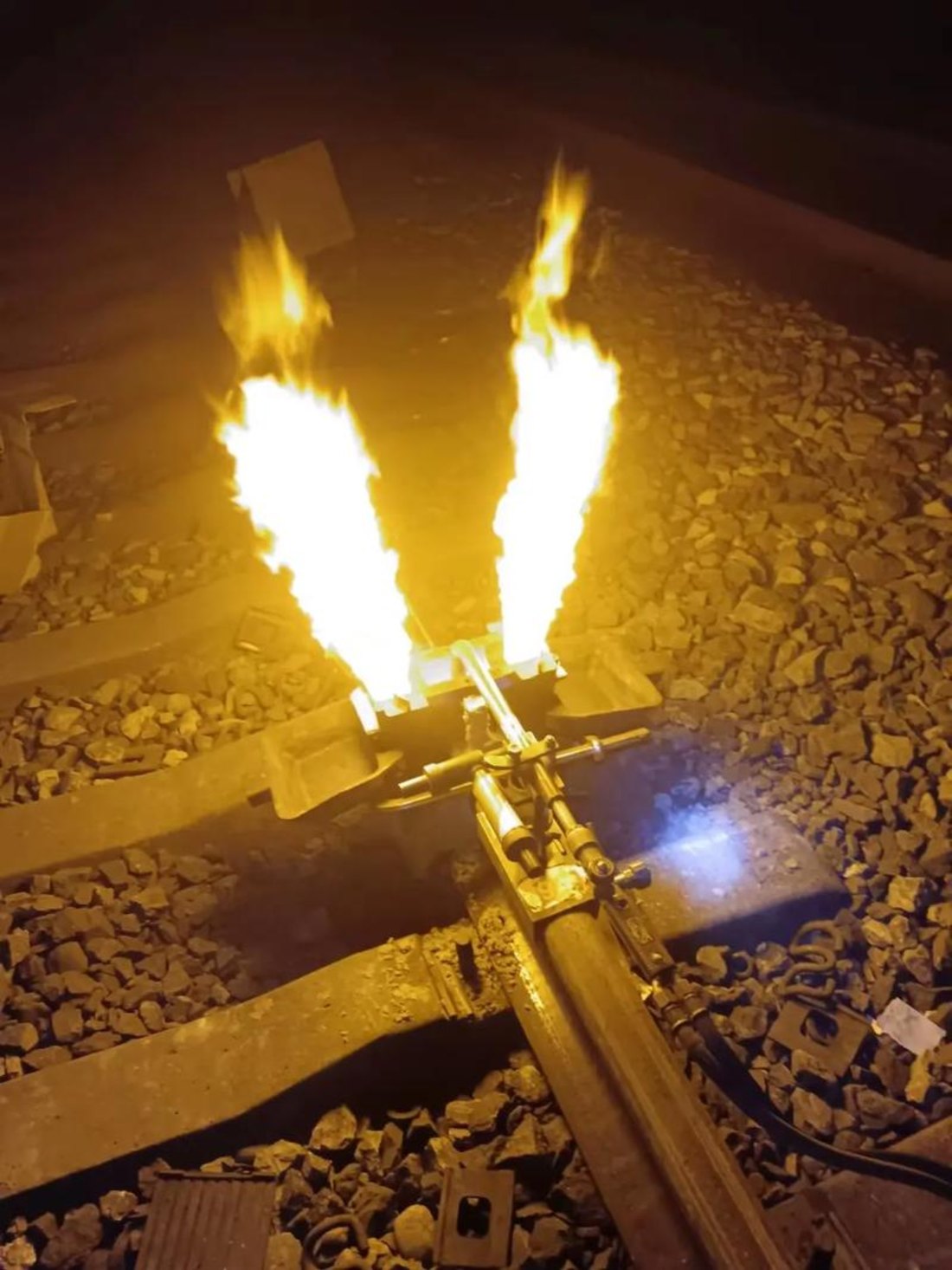
5. Preheat. Oxygen and propane through a burner, applied to both rail ends. The preheat target is process- and standard-dependent, and the figures in circulation differ because they refer to different measurement positions — a value measured at the rail face is not the same as a value measured 50 mm from the weld centre. EN 14730-1 requires a system that maintains gas flow down to 0 °C and caps preheat time at 10 minutes regardless of profile and grade. Preheat must be verified with a thermometer, not by eye, and it must be even across the section: a hot head and a cold foot is worse than a uniformly slightly cool joint.
6. Pour. Ignite the charge. The reaction completes in roughly 20 seconds and the pour follows automatically. The operator's job at this point is to stand clear and observe — there is nothing to adjust.
7. Cool. Natural air cooling, undisturbed. The minimum before stripping the mould is usually quoted as 10 minutes, and the practical failure here is impatience: stripping early, or quenching with water, changes the cooling rate and therefore the hardness and residual stress in the weld and the heat-affected zone.
8. Strip, cut the risers, grind. Remove the mould, cut off the runners and risers with a hot chisel while the weld is still warm, then grind. Grinding has two stages in good practice: hot grinding of the base and sides while the weld is above roughly 400 °C, and cold finishing below 100 °C to the final profile tolerance.
Table 2 summarises the checkpoints, which is the part worth printing and taking to site.
| Step | Checkpoint | What failure looks like later |
|---|---|---|
| Cut | Saw cut, square within tolerance, no thermal damage | Lack of fusion at one face; a weld that passes inspection and fails in service |
| Clean | No rust, scale, grease or moisture within the fusion zone | Slag and oxide inclusions at the head or web |
| Align and gap | Straight edge over 1 m; gap within ±2 mm; mould within ±2 mm | Wrong collar geometry, misaligned running surface, gauge deviation |
| Mould and seal | Every flange sealed; no visible gaps | Steel escape, cold shut, incomplete weld |
| Preheat | Verified by thermometer, even across the section, within the time cap | Lack of fusion, especially at the web and foot |
| Pour | Full reaction, clean separation of slag | Porosity, shrinkage cavity under the riser |
| Cool | Minimum time before stripping, no quenching | Hardness out of band, cracking, residual stress |
| Grind | Hot grind above 400 °C, cold finish below 100 °C, profile to template | Rail burn, dipped weld, poor ride quality, dynamic impact |
Thermite Welding Equipment and Consumables
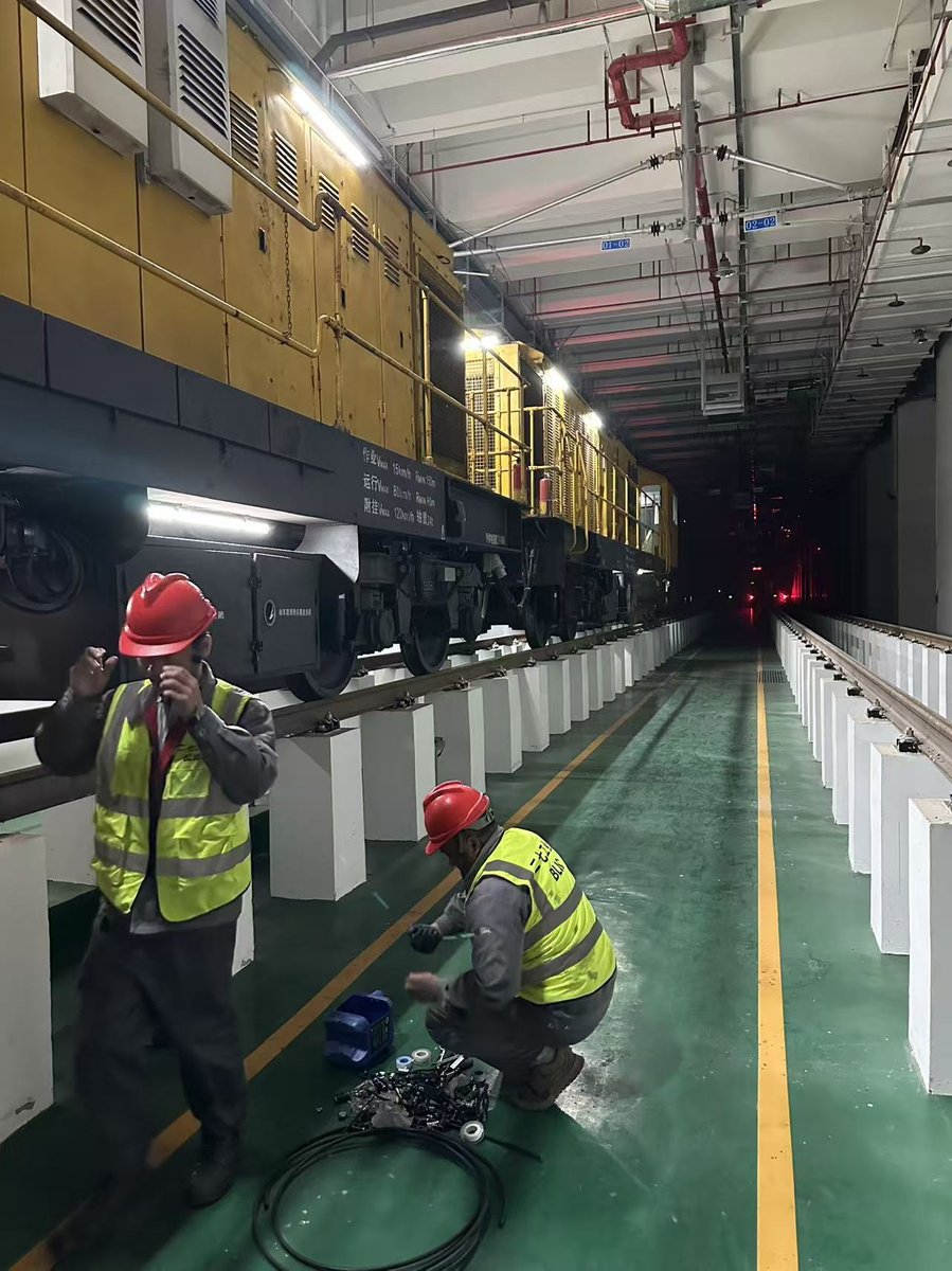
The capital equipment for aluminothermic welding is remarkably cheap, which is part of why the process spread as widely as it did. A basic kit — clamps, straight edge, gap gauges, burner set with flashback arrestors, thermometer, hot chisel, slag pan — is a modest purchase. The recurring cost is the one-shot consumable: crucible, charge, mould.
Three consumable decisions matter more than unit price.
Charge grade must match rail grade. A charge formulated for a standard carbon rail will not produce the hardness required on a head-hardened or microalloyed rail. The result is a soft weld in a hard rail — a strength mismatch that shows up as batter and then as a defect at the weld toe. This is one of the few cases where the consumable genuinely is the root cause.
Mould must match profile exactly. Moulds are made for specific profiles. A generic mould, or a mould for the right section but the wrong profile, produces a collar that is wrong in volume and shape. The weld may look acceptable and still have inadequate fusion at the web because the cavity did not seal against the rail correctly.
Batch traceability is not bureaucracy. EN 14730-2:2021 makes a welding quality traceability system mandatory for approved contractors, and requires recording of parameters including flux batch and weather conditions. The reason is diagnostic: when a joint fails, the first question is whether other joints from the same charge are also at risk. Without batch records, that question cannot be answered, and the operator is left with either a network-wide inspection or none.
Storage matters as much as specification. Crucible linings and charges absorb moisture, and a damp charge produces porosity and can react violently. Store sealed, dry, and use within the manufacturer's shelf life — a store room that is convenient to the trackside but unheated is a false economy.
Thermite Welding Equipment: What to Buy and What to Share
A trackside welding outfit needs three categories of equipment, and the useful distinction is between what must be per-crew, what can be shared across crews, and what should not be purchased at all because the system supplier has to control it.
Per-crew, because a shared item becomes a waiting item. Clamps, gap gauges, straight edge, burner set with flashback arrestors, thermometer, hot chisel, slag pan. These are cheap, they are needed at every joint, and any one of them missing stops the crew. The thermometer deserves a specific mention: it is the cheapest item on the list and the one whose absence most reliably destroys quality, because without it preheat becomes an assumption.
Shared across crews, because utilisation is low. Rail saws, the alignment equipment used for setting multiple joints in one possession, fume extraction for tunnel work, and the ultrasonic set if the operator keeps inspection in-house. Sharing works when the sharing is scheduled rather than ad hoc.
Not purchased, because the supplier must control it. Crucibles, charges and moulds. These are the items where substitution produces defects that surface months later, and where the traceability chain from batch to joint is the only thing that makes a failure investigation possible. Buying consumables on unit price alone, or mixing charges from different suppliers into one store, breaks that chain.
One further equipment question is worth settling early rather than at the first cold snap: gas supply. EN 14730-1 requires a preheat system that can maintain its flow down to 0 °C. A burner set that works in summer and freezes its regulator in winter will cost a possession the first time the temperature drops, and the failure looks like a crew problem rather than an equipment specification problem.
Aluminothermic Welding Quality Control
Quality control in this process is mostly about controlling the conditions rather than inspecting the result, because many of the defects that matter are invisible from the surface.
Table 3 sets out the acceptance values that matter most, drawn from the European framework.
| Parameter | Value | Source / note |
|---|---|---|
| Welding gap tolerance | ± 2 mm | EN 14730-1 |
| Mould positioning tolerance | ± 2 mm longitudinally | EN 14730-1 |
| Blowpipe height tolerance | ± 3 mm | EN 14730-1 |
| Preheat time cap | 10 minutes, any profile and grade | EN 14730-1 |
| Ultrasonic rejection level | FBH 5 mm | EN 14730-1, Annex C |
| Heat-affected zone width, non-heat-treated rail | ≤ 40 mm | EN 14730-1 ch. 7.1.3 |
| Heat-affected zone width, heat-treated rail | ≤ 60 mm | EN 14730-1 ch. 7.1.3 |
| Heat-softened zone width | ≤ 30 mm | EN 14730 Annex J |
| Fatigue strength | ≥ 210 N/mm² at 5 million cycles | EN 14730-1 Annex K, staircase method |
| Vertical deviation, Class A / B | ≤ 0.3 mm / ≤ 0.5 mm | EN 14730-2:2021 |
| Slag inclusion depth, Class A / B | ≤ 1 mm / ≤ 3 mm | EN 14730-2:2021 |
| Grinding length, Class A / B | 600 mm / 900 mm | EN 14730-2:2021 |
Two of those rows deserve explanation because they are frequently misunderstood.
The heat-affected zone limit is a quality statement, not a process preference. A weld with a HAZ wider than the specified limit means too much heat went in, or the preheat was excessive, or the cooling was too slow. All three change the metallurgy of the parent rail beside the weld, and that softened or hardened band is where fatigue damage will initiate.
The grinding length is part of the acceptance criteria, not a finishing choice. Classes A and B differ in both vertical deviation and grinding length, because a shorter ground length leaves a steeper transition. That transition is where dynamic loads spike, and it is the mechanism behind the failure mode described in our analysis of grinding length at weld seams.
Rail Welding Procedure Qualification: The Document Behind the Joint
Every parameter in this article — the gap tolerance, the preheat position, the cooling time, the grinding class — exists because a procedure says so. A welding procedure specification is what turns a competent crew's good habits into a reproducible process, and the qualification that sits behind it is what an auditor will ask for when a joint fails.
What a procedure specification has to contain, how the qualification testing is carried out, how inspection frequency is set and what records get retained are covered in our guide to rail welding procedure qualification — the documentation layer that surrounds the process described here. The two are not the same document and both are needed: this article describes what has to happen, that one describes how you prove it happened the same way every time.
What the welder has to prove
The process cannot be verified from the finished joint alone, which is why the European framework regulates the person as tightly as the procedure.
EN 14730-2:2021 sets out the qualification route. Training is four weeks for an inexperienced welder and two weeks for one with prior experience. The theoretical assessment is 25 questions including five compulsory ones on key process steps, and the practical assessment covers a set of process checks defined in the standard's annex, with mould sealing, preheat flame adjustment and final grinding accuracy treated as veto items. The welding licence has a validity period of up to five years.
Contractor approval is separate from welder qualification, and requires a welding coordinator qualified to EN ISO 14731, a materials traceability system, and equipment calibration at intervals not exceeding six months. Records are retained for years, because a joint that fails in year eight needs a paper trail from the day it was made.
Some infrastructure managers go further than the minimum. German practice, for example, expects a welder to complete at least 50 qualified welds a year to keep the qualification current — a recognition that this is a skill whose edge dulls with disuse.
Welding of Rails in Cold and Wet Conditions
Two environmental conditions change the risk profile of this process, and both are common enough to be worth a specific routine.
Cold. Below about 5 °C the rail is a heat sink with much greater capacity than in summer, and the preheat that works in July will not bring the section to the same uniformity in January. The consequences are uneven fusion at the foot and a steeper thermal gradient through the weld on cooling. Practical responses are a longer preheat at the same measured temperature, sheltering the joint from wind, and pre-warming the mould. What is not acceptable is adding preheat time without a thermometer check, because the failure mode of over-preheat — a heat-affected zone beyond the 40 or 60 mm limit — is as bad as under-preheat and less visible.
Wet. Moisture is the direct cause of porosity and, in the worst case, of a violent reaction in the crucible. Rain on the rail ends, condensation on a cold mould, a damp charge or a damp crucible lining all introduce hydrogen into the weld. The routine is to shelter the work, dry and pre-warm the mould, use a charge from a sealed pack, and stop if water is reaching the mould cavity. A weld made in rain without shelter is a gamble, and the porosity it produces may not appear in a visual inspection.
Tunnel and confined-space work adds a third condition, because the reaction produces large volumes of fume. EN 14730-1 anticipates this by requiring a process adapted for use with a filtration system where welding takes place in tunnels — an operational planning requirement, not a welding one, but one that decides whether the joint can be made at all in the available possession.
Common defects and what they actually mean
Table 4 maps the four defect families to their usual causes, because the cause determines the fix.
| Defect | Usual cause | The fix that actually works |
|---|---|---|
| Porosity | Damp charge, damp crucible lining, or moisture in the mould | Dry storage, shelf-life control, pre-warm the mould in humid conditions |
| Slag or sand inclusion | Poor sealing, dirty rail ends, disturbed pour | Seal every flange, clean to bright metal, do not move the assembly during the pour |
| Lack of fusion | Insufficient or uneven preheat, gap out of tolerance, cold rail | Verify preheat by thermometer at the specified position, control gap, preheat more in cold weather |
| Cracking | Cooling too fast, stripping early, quench, wrong charge grade | Enforce minimum cooling time, no water, correct charge for rail grade |
The repeated theme in that table is that three of the four families trace back to preparation and discipline rather than to consumable quality. When an operator reports a run of failures, the productive first question is what changed in the preparation routine — a new crew, a rushed possession, cold weather, a different store location — rather than which supplier's charge was used.
When Aluminothermic Is the Wrong Choice
This article assumes aluminothermic welding is the method being used. That is often the right assumption at the trackside — the process needs no plant, works in a short possession, and handles turnouts and closures that a welding train cannot reach — but it is not always the right answer.
Where fatigue life governs, where the joints are numerous and repeatable, or where a welding plant can be brought to the work, flash butt welding produces a stronger, more consistent joint and is the better choice on both engineering and whole-life cost grounds. The comparison is not close on weld quality; it is close on access and mobilisation, which is why both processes persist.
The trade-off, and the decision path for choosing between them, is set out in our comparison of thermite welding versus flash butt welding. If you are specifying a joint and have not made that choice explicitly, make it before the procedure is written — the acceptance criteria and the inspection regime differ.
Aluminothermic Welding and Grinding: Where the Two Meet
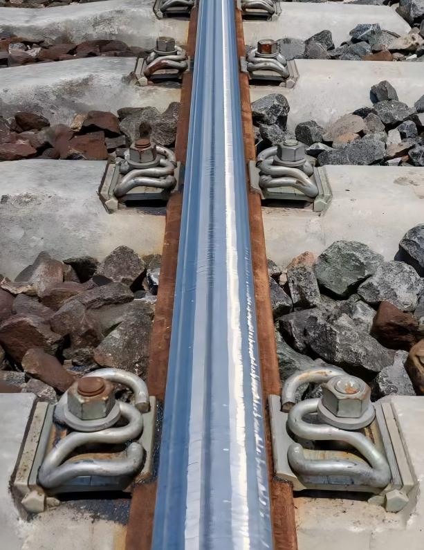
A finished weld is not a finished joint. The aluminothermic process leaves a collar of cast steel around the rail, and the running surface has to be restored to profile within tolerance. That transition — from the cast collar, through the heat-affected zone, into unaffected rail — is geometrically the hardest part of the whole joint to get right.
Two consequences follow, and they are the reason this site keeps returning to grinding.
The grinding specification is part of the weld specification. Classes A and B in EN 14730-2 differ by grinding length as well as by vertical deviation, which means the acceptance of a weld depends on how far along the rail the grinding was carried out. A weld ground to class A geometry over a class B length is not a class A weld.
Wheel choice determines whether the grinding achieves the specification. A wheel that cuts too aggressively on the hard cast collar will burn or over-cut the softer heat-affected zone beside it, producing a dipped surface that fails the straight-edge check. The relationship between wheel specification, cutting behaviour and the transition zone is covered in our complete weld-to-grind workflow guide and, for the specific failure mode, in the analysis of grinding length.
Acceptance, Records and the Paper Trail
A weld is accepted on three things: its geometry, its internal soundness, and its documentation. Most operators are rigorous about the first, inconsistent about the second and weak on the third — and the third is what decides whether a failure in year eight can be diagnosed.
Geometry is checked against the class specified. Vertical deviation, horizontal alignment and gauge effect are all measurable at the joint with a straight edge and a gauge, and the grinding length is measured because it is part of the class definition rather than a finishing preference. The measurement has to be recorded against a joint identity, not against a shift.
Internal soundness is established by ultrasonic testing at the frequency the infrastructure manager sets, with the rejection level defined. What matters operationally is that the joints selected for testing are genuinely representative. If the joints tested are always the ones the crew was happiest with, the sampling tells you nothing.
Documentation is the part that pays for itself years later. The minimum record for each joint is: location and rail identity, date and ambient conditions, welding system and charge batch, the welder's identity and licence, the measured gap and preheat, the cooling time, the geometry result, and the ultrasonic result if tested. EN 14730-2:2021 makes a traceability system mandatory for approved contractors and requires records to be retained long-term, and there is a good reason: when one joint fails, the immediate question is which other joints share its batch, its crew or its weather.
Table 5 sets out the minimum record set and what its absence costs.
| Record | What it enables when a joint fails | Cost of not having it |
|---|---|---|
| Location and rail identity | Finding the joint at all, and relating it to rail supplier and grade | A failed joint that cannot be relocated confidently |
| Date, ambient temperature, weather | Correlating failures with cold or wet conditions | A cluster that looks random |
| Welding system and charge batch | Identifying every other joint from the same batch | A network-wide inspection or none at all |
| Welder and licence number | Correlating failures with a person or a training gap | A suspicion that cannot be resolved |
| Measured gap and preheat | Testing the procedure against what was actually done | An unfalsifiable assumption that the procedure was followed |
| Cooling time | Ruling out early stripping | The most common self-inflicted cause left unexamined |
| Geometry result | Establishing whether the acceptance class was met | A dispute with the contractor that cannot be settled |
| Ultrasonic result | Proving the inspection happened at the specified level | An inspection regime that exists only on paper |
The reason this table is long is not bureaucracy. It is that every one of those rows answers a question that will be asked, and the only cheap time to answer it is at the trackside, in the fifteen minutes while the joint is being made.
Five Assumptions That Cost Operators Money
After enough failure investigations, the same misjudgements recur. Each one is reasonable on its face, and each one is expensive.
"The consumable is the variable, so change the consumable." It is the easiest thing to change and the hardest to prove. But preheat, gap, sealing and cooling discipline account for more failures than charge quality, and those are all free to fix. The diagnostic order should be preparation first, consumable third.
"The weld passed inspection, so it is a good weld." Inspection samples and inspection cannot see everything. A joint with a heat-affected zone beyond the limit passes a straight-edge check and a visual, and then initiates fatigue damage in the softened band beside the weld. Geometry acceptance and metallurgical acceptance are different tests.
"Faster cooling gets the line back sooner." It does, and it also changes the hardness and residual stress in the weld and the heat-affected zone. The ten to fifteen minutes of undisturbed cooling is the cheapest insurance in the whole process, and quenching is the most common self-inflicted defect.
"A qualified welder produces qualified welds." Qualification establishes that a person could make the joint; it does not establish that they are making it on a cold, wet, rushed night in a short possession. This is why the standards require periodic requalification and why some infrastructure managers require a minimum number of welds a year to keep the licence current.
"The grinding is a separate job." The grinding class is part of the weld acceptance definition. A weld ground shorter, or ground with a wheel that burns the adjacent softer zone, fails the standard even if the casting was perfect. The two operations are one specification, which is why the finishing side deserves the same planning attention as the pour.
Frequently Asked Questions
What is aluminothermic welding?
A casting process that joins rail ends by pouring superheated steel, produced by the reaction of iron oxide and aluminium, into a mould sealed around the joint. The rail ends are preheated but do not melt; the cast steel bonds to them. It is the standard field method for joining rails where a flash butt welding plant cannot be brought to the track.
How long does an aluminothermic weld take?
A trained two-person crew completes a joint in roughly fifteen to twenty minutes: a few minutes of cutting, cleaning and alignment, then preheat (typically 8 to 15 minutes depending on the system and the ambient temperature, capped at 10 minutes under EN 14730-1), a pour of a few seconds, and 10 to 15 minutes of cooling before the mould is stripped. Grinding follows.
What preheat temperature should be used?
It depends on the welding system and on where the temperature is measured. Figures in circulation typically range from 150 to 350 °C at a defined distance from the weld, rising to 800 to 900 °C at the rail face in some procedures for the flame itself. The two are not interchangeable. What matters operationally is that the procedure states the measurement position and that it is verified with a thermometer at that position.
Is thermite welding as strong as the rail?
A correctly made aluminothermic weld reaches roughly 85 to 90% of parent rail tensile strength, with base hardness in the region of HB 280 to 350 depending on rail grade and charge. That is adequate for the application, which is why the process is used on mainline and turnout work across most networks. It is not equivalent to a flash butt weld, and where fatigue life governs, that difference matters — see the thermite versus flash butt comparison.
Why do aluminothermic welds fail?
The dominant causes are lack of fusion from insufficient or uneven preheat, incomplete mould sealing allowing steel escape, gap outside tolerance, and cooling too fast through early stripping or quenching. Consumable quality is a real cause but is responsible for a minority of failures. Any investigation should start with the preparation record for the joint in question.
How long before the mould is removed?
Ten to fifteen minutes of undisturbed air cooling is the usual figure, and the requirement is a minimum rather than a target. Removing the mould early, or cooling the weld with water to get the line back sooner, changes the cooling rate and therefore the hardness and residual stress in the weld and the heat-affected zone. It is the most common self-inflicted defect in the process.
Does the weld need ultrasonic testing?
Not every joint, but a defined proportion, and the rejection level is specified. Under EN 14730-1 the ultrasonic rejection level is FBH 5 mm. The proportion tested is set by the infrastructure manager, and it is normally higher for the first joints of a new procedure or a new crew. Our guide to rail welding procedure qualification sets out how the inspection regime and sampling frequency are documented.
Welding Systems, Consumables and Training
RailwayCare supplies rail replacement and welding systems for track work, alongside the grinding wheels that finish the joint. If you are setting up or re-qualifying an aluminothermic process, we can work through the procedure, consumable specification and finishing sequence with your engineering team.
For the documentation side — what a procedure specification has to contain, how inspection frequency is set, and what records get retained — the rail welding procedure qualification guide covers it. For the process comparison that decides whether aluminothermic is right for a given joint, see thermite versus flash butt welding. For the wider maintenance programme, the rail maintenance solution pages set out the context, and grinding training is available for crews who need the finishing side brought up to standard. Project enquiries go through project cooperation, and our background is in about RailwayCare.
WhatsApp: +86 15072332788 Email: simon.wang@railwaycare.com
RailwayCare (Wuhan Huatie Ruijie Rail Transit Technology Co., Ltd.) — your professional partner in rail grinding, with Molaton grinding wheels field-proven on high-speed, heavy-haul and metro lines since 2004.