Railroad Thermite Welding: Cutting, Replacement and Weld Inspection in One Possession
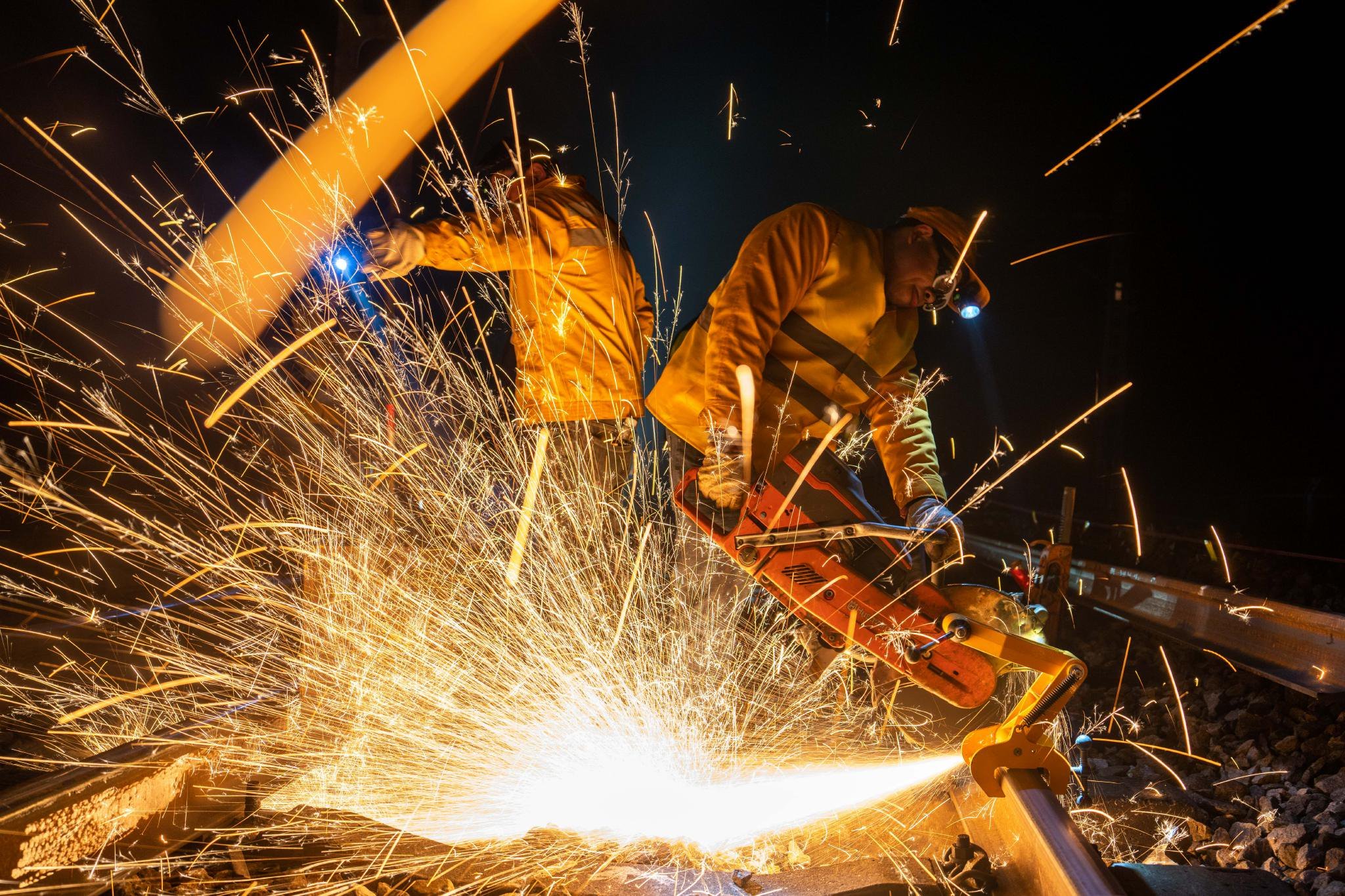
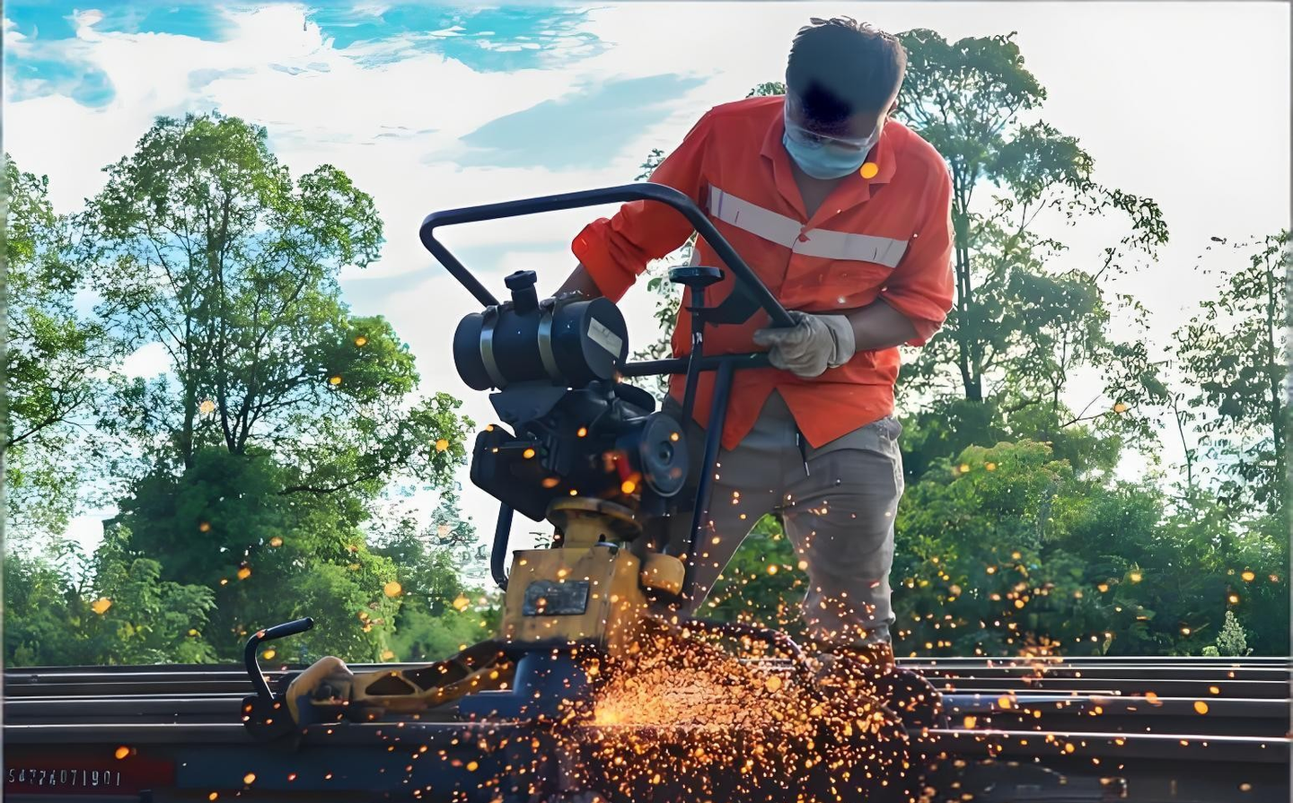
A defective rail found on a trunk line has to be cut out, replaced, welded and inspected before the possession window closes — and if any of those five operations goes wrong there is no second night to put it right. This guide sets out the full railroad thermite welding workflow as it was executed on a mixed passenger–freight corridor inside the China Railway Wuhan Bureau network, stage by stage, with the parameters that were controlled and the acceptance criteria the finished joints were measured against. The section sits on a mixed passenger–freight trunk line inside the Wuhan Bureau network, carrying a dense daily mix of passenger services and heavy freight. Track inspection identified a defective rail — one of the defect types that cannot be ground out and must be removed — and the decision was taken to replace the affected length rather than attempt further in-track repair. The scope was deliberately narrow: one replacement rail in standard milled length, producing two welds, one at each end. That scale is typical of defect-driven rail replacement, and it is exactly the case where process control matters most. A small job leaves no room to absorb a poor weld, because there is no second joint to compare against and no spare possession to redo the work. The window was a single possession. Working backwards from handback, every operation had to be sequenced so that the weld had cooled, been ground and been inspected before the section was released to traffic. There is also a live policy question about welding methods, and it is worth being precise about it, because the method choice here follows the rules rather than working around them. Current guidance from China Railway is that new-build and reconstructed lines should use flash-butt or gas-pressure welding in place of thermite welding. The reason is documented: thermite joints have lower strength than the parent rail, are prone to surface depression, and require far more frequent inspection than flash-butt or gas-pressure welds — a recurring operating and maintenance cost. The guidance followed a weld failure on a turnout closure rail that was traced back to the process. That guidance has an explicit boundary, however. Under TB 10082—2017, clause 8.0.6, closure welds inside turnouts and on the sections joining a turnout to open line may still be made thermitically. The same logic applies in practice to single-point rail replacement on an existing line: a mobile flash-butt unit needs plant, power and track access that a defect repair of a few metres does not justify, and the closure joint is a field weld made between two rail ends already in track. So the method was selected on its merits, not by default. Railroad thermite welding needs no large plant, no mains power and no long set-up; one crew can complete a joint inside a possession. The trade-off is the one the policy names — a joint that is metallurgically different from the parent rail, and that has to be verified rather than assumed. That is why every parameter below is controlled and recorded, and why the final operation of the job is an inspection rather than a visual check. The whole job resolves into five operations, performed in strict sequence: The sequence matters because errors propagate forward. A cut face that is not square turns into an alignment problem; an alignment problem turns into a depressed joint; a depressed joint turns into a joint that fails inspection and has to be cut out and welded again — inside a window that has already been partly spent. The first cut is a removal cut. Its job is to take out the defective length cleanly and quickly, leaving a usable end face at each side of the opening. At this stage the priority is cutting capacity and independence from site services, so the work used a fuel-powered rail cutting machine with resin-bonded cutting discs. The machine needs no mains supply and no external power pack, which matters on a trunk line where the nearest supply may be hundreds of metres away. Cutting performance in this class of machine runs at roughly 2.5 to 3 rail cuts per disc, with a single cut through a rail section taking approximately 3 to 6 minutes depending on rail grade and condition. Quality control at this stage is simple to state and easy to get wrong. There must be no thermal damage — no burn marks and no metallurgical discolouration on the cut face; no burrs and no edge cracking on the rail head, web or foot; and a clean, perpendicular cut face that the later alignment work can build on. Mechanical cutting is used rather than flame cutting precisely because a flame cut introduces a heat-affected zone at the very end of the rail that has to carry the weld. A rail end that has been thermally altered before the weld is poured starts the joint at a disadvantage. The same tooling logic applied to a longer track-replacement job is set out in our guide to rail replacement inside a blockade window. With the defective section removed, the replacement rail is brought in and set into track. Two things are happening at once here: the new rail has to sit correctly in plan and level, and the track either side of the opening has to be held so that the gap does not move while the work is done. In practice that means locking the line over a distance either side of the joint — typically the rail ends within about 15 m are secured against movement — and releasing the fastenings on the three to five sleepers immediately adjacent to each joint so the rail ends can be positioned freely. Ballast is cleared from the cribs to a depth of around 100 mm so the rail foot and the mould can be worked on properly. The replacement rail is set so that the finished joint geometry, not the intermediate position, is what the alignment is measured against. There is one deliberate exception to perfect flatness, and it belongs to the welding stage rather than this one: the joint is set marginally high so that the weld does not finish as a depressed joint. This is the operation most often underestimated in a rail replacement, and it is the reason the job cannot be done with a single cut. The first cut removes the defect. The second cut sets the gap that the weld will fill. The two are different operations with different tolerances, and the second one is a measurement job with a saw attached to it. The gap is specified at 26 ± 2 mm. Get it below the tolerance and preheating becomes uneven, because the burner flame cannot develop properly in a gap that is too tight. Get it above and preheating is incomplete and the filler metal may not be sufficient to complete the joint. Neither error is visible from the surface of the finished weld — both show up later, in inspection or in service. Two further controls sit with this cut. End-face perpendicularity must be within 0.8 mm, which is what allows the two rail ends to meet properly through the web and foot rather than only at the head. And the saw-cut quantity is calculated and confirmed before any cutting: rail is cut short, not long, the length removed is derived from the measured gap, re-checked, and only then cut. Where the gap is excessive, the rail ends are drawn together with a rail tensor rather than cut again. For this cut the work switched tools, using the RailwayCare RCS-L50 lithium-powered rail saw. The reasoning is that the closure cut is a precision operation and this saw is the precision instrument in the kit. A 72 V lithium battery pack driving a 5.0 kW brushless motor cuts 60 kg/m rail in about 120 seconds, with stable speed and no power attenuation through the cut. The all-steel construction absorbs vibration, which is what protects cut-face perpendicularity, and the absence of exhaust emission means the same tool can be used inside a tunnel or between platforms where a combustion engine is unwelcome. The specification is set out on the RailwayCare RCS-L50 lithium-powered rail saw product page. After cutting, both rail ends are prepared for welding. The end faces and the surrounding rail surfaces — typically about 150 mm back from each end — are cleaned with a wire brush and grinder to remove oxide, oil, paint and rust. Welding over scale, or over a damp or oily end face, is a direct route to porosity in the finished joint. The weld itself is a sequence of timed steps, and the finishing that follows it is not an optional extra — the reasoning is set out in our analysis of thermite welded rail joints and why grinding is half of the job. Alignment. The two rail ends are brought into line using purpose-made alignment equipment with a fine vertical adjustment. Horizontal alignment, longitudinal alignment and twist all have to be corrected, and the rail is never struck or forced into position. A one-metre straightedge is placed against the rail head side to confirm the ends are true, and the same check is repeated at the foot and web. The joint is deliberately set 1.5 to 2 mm high to compensate for contraction and to prevent the finished joint sitting low. Moulding and sealing. The sand mould is checked for damage and damp, trial-fitted to the rail, and clamped in place. Sealing sand is packed into the sealing grooves around the mould and rail, and the slag pan is sealed too. This step is unglamorous and it is where a poor job announces itself: an imperfect seal lets molten steel escape as a run-out, and the joint is lost. Preheating. Oxygen and liquefied petroleum gas are used to bring the rail ends and the mould up to temperature and drive off residual moisture. For 60 kg/m rail the preheat runs about five minutes with an oxygen flow of roughly 3,800 litres per hour, bringing the rail ends to a dull-to-bright orange, around 800 to 900 °C. Flame conditions — pressure settings, flame colour, the position of the burner relative to the gap — are all set before ignition, and the flame emerging from the mould vents on both sides is watched to confirm the heating is even. Pouring. The crucible charge is ignited within 30 seconds of preheating being completed. The reaction then runs, and the time from ignition to the start of pouring should fall between 15 and 35 seconds. The reaction temperature exceeds 2,400 °C — high enough that the mould, built for about 3,000 °C, is what contains it. The consumable set used on this work is the RailwayCare TWS thermite welding system. Crucible, slag pan, mould clamps and top mould are removed on a timed schedule measured from ignition: crucible at the end of pouring, slag pan at about two minutes, clamps at about five. Push-off and grinding. At roughly six and a half to seven minutes from ignition, the hydraulic push-off machine shears the excess weld metal from the rail head, leaving a residual of between 0.5 and 1.5 mm. Two-stage grinding follows. Hot grinding is completed before the section is released to traffic, leaving the weld metal slightly proud — no less than 0.8 mm above the running surface — so that finishing takes the weld down to the rail, not the rail down to the weld. Cold finishing, once the joint has cooled, brings the weld crown to within 0.2 mm and blends it into the surrounding rail so that there is no step, no dip and no abrupt transition in the contact band. The acceptance figures that this finishing is measured against are compared in our guide to rail grinding acceptance standards. This grinding stage is not cosmetic. A weld finished with the wrong profile, or blended over too short a length, creates a wheel–rail impact at the joint on every passage — the mechanism, and the blend length required to avoid it, are covered in our article on grinding length in rail weld seam finishing. The final operation is the one that decides whether the work counts. A finished joint is inspected by ultrasonic testing before the section is returned to traffic — not sampled, and not deferred to the next routine patrol. Timing and surface condition. Testing is carried out after push-off and grinding are complete, with the joint cooled to below 40 °C. Inspecting hot is not an option; the joint has to be at or near ambient rail temperature. The probe surfaces — rail head running surface, both sides of the head, both sides of the foot and the upper part of the foot corner to about 30 mm — are ground back to original rail surface so that the probes couple properly. Weld flash, loose slag and heavy corrosion all have to be off the surface first. Scan coverage. The joint is scanned across its full section, using both single-probe and dual-probe methods. In practice this means a combination of probe angles — 0°, 37°, 70° and twin 45° — covering the head, web and foot, with particular attention to the foot corner, which is a stress concentration area and the place where a defect most often hides. Who carries it out. Inspection at this level is performed by personnel holding a level II or higher non-destructive testing qualification, with specific training and certification in rail joint inspection. The instrument has to meet the applicable rail ultrasonic testing instrument standard, and sensitivity is set against reference blocks before the scan begins. Rejection. A joint that fails is not patched and not left in track. Trigger conditions include a back-wall echo 16 dB or more below that of a sound joint, or defect indications above the permitted equivalent size — for example, in the foot corner within 20 mm of the foot edge, an equivalent of φ3 minus 6 dB in dual-probe testing, and φ3 flat-bottom hole equivalent elsewhere. Any joint meeting a rejection condition is cut out and welded again, this time starting from a corrected gap. Records and marking. Every joint is identified. The joint number is marked on the rail web, and a welding record is completed covering the time, the personnel, the joint location, rail type, welding material batch, the gap, reaction time, preheat time, oxygen pressure and weather conditions. The record is not paperwork for its own sake. A thermite joint in service requires full-section inspection at least every six months, and the record is what makes that schedule traceable to a specific joint at a specific location. Both joints in this work passed inspection and the flatness checks against the allowance for the line speed class, and no cut-out and re-weld was required. Handback is governed by temperature as much as by geometry. Trains are not allowed over the joint while the weld metal is above 300 °C, and the first train through is generally released 20 to 40 minutes after welding, depending on air temperature and how quickly the joint cools. Before the section is released, the finished work is checked against the acceptance criteria for the line: joint flatness within the allowance for the speed class, weld crown brought down to within 0.2 mm, no step or dip at the joint, and gauge, cross-level and alignment restored across the replaced length. The measurement practice behind those checks is the same one used for rail wear measurement and grind-or-replace decisions. The site is then cleared, tools and plant are removed beyond the clearance limits, and the welding records and joint identification are completed and filed. What the operator carries forward is the permanent record: two joints on a named line at known locations, welded on a recorded date with a recorded gap, preheat time and welding material batch, with a full-section inspection result on file — and a repeat inspection due within six months. Using two cutting machines on a two-joint replacement looks like duplication. It is not; it is a deliberate split between two different tolerance regimes. The removal cut is a capacity job. It is made in a rail section that may be hard, in open track, with the priority on getting through the rail reliably and starting the next operation. A fuel-powered machine with resin discs does this without depending on anything the site has to provide. The closure cut is a metrology job. The outcome is a gap held to 26 ± 2 mm inside a rail that is already fixed in position, with an end face perpendicular to within 0.8 mm, and the cut length is calculated rather than estimated. That calls for a saw with stable speed through the cut, no power fall-off at the end of a long cut, and enough rigidity to hold the cut face square. A lithium-powered saw with a brushless motor and a stiff frame meets that requirement, and it does so without exhaust emission — which matters when the work is inside a tunnel or at a station. The general lesson is that tool selection follows the tolerance of the operation, not the convenience of owning one machine. This job assigned the two tools to the two cuts that match what each of them is good at. Three points transfer to any defect-driven rail replacement, on any network. First, the second cut is the weld. The gap and the end-face condition set the quality ceiling for the joint. Everything that follows — alignment, moulding, preheating, pouring — can only work with what the cut provided. Calculate, confirm, then cut. Second, inspection timing is not negotiable. Ultrasonic testing on a joint that is still hot does not give a valid result, and the probe surfaces have to be prepared before the instrument goes on. Both take time, and both have to be inside the possession plan from the beginning rather than discovered at the end. Third, the welding record is the maintenance plan. A thermite joint carries a six-monthly full-section inspection requirement for as long as it is in track. A record that identifies the joint, the date and the parameters is what makes that requirement executable. Without it, the joint is an unlabelled item of risk on a busy line. RailwayCare supplied the cutting, welding and grinding equipment and consumables for this work, together with the work sequence and parameter set used by the site crew. The same equipment set covers rail maintenance projects across cutting, welding, grinding and inspection. The questions below are the ones operators raise most often when they plan a replacement like this one. Because the guidance that prefers flash-butt welding also defines where it is not practical. New-build and reconstruction work is expected to use flash-butt or gas-pressure welding, but closure welds inside turnouts and at the junctions between a turnout and open line may still be made thermitically, and the same applies to a field joint on an existing line where mobile flash-butt plant cannot be justified for a few metres of rail. The condition attached to that permission is stricter process control and more frequent inspection. The first cut takes out the defective length; the second sets the gap the weld has to fill. The gap is specified at 26 ± 2 mm because preheating depends on it: too tight and the flame cannot develop, too wide and the preheat is incomplete and the filler may not fill the section. The second cut also sets the end-face perpendicularity, which is what allows the two ends to meet properly through the head, web and foot. After push-off and grinding are finished and the joint has cooled below 40 °C. The probe surfaces have to be ground back to original rail surface first — the running surface, both sides of the head, both sides of the foot and the upper foot corner — and weld flash and slag removed. A joint still above ambient temperature cannot be tested reliably, which is why cooling time has to be planned into the possession rather than treated as dead time. It is cut out and welded again. Thermitically welded joints are not reworked in place. Rejection is triggered by conditions such as a back-wall echo 16 dB or more below that of a sound joint, or defect indications above the permitted equivalent size in the head, web or foot. Because the joint is removed rather than repaired, a failed inspection costs the welding work and the time to re-cut and re-pour — which is the reason the earlier stages are controlled as tightly as they are. The controlling figure is joint temperature, not time: trains are not released over the joint while the weld metal is above 300 °C. In practice the first train is usually allowed through 20 to 40 minutes after welding, depending on ambient temperature and cooling rate. Hot grinding is completed before handback, and cold finishing follows once the joint has cooled. Yes. A thermite joint in track requires full-section ultrasonic inspection at least every six months, and the interval is shortened on heavily trafficked sections, in tunnels and on bridges, on small-radius curves and on steep gradients. This recurring requirement is the main reason the joint must be identified and recorded when it is made. RailwayCare supplies rail cutting, thermite welding, weld grinding and inspection equipment and consumables, and supports operators with work sequences, parameter sets and crew training for defect-driven rail replacement. If you are planning rail replacement work — single-point repairs, turnout closure welds or a full maintenance programme — send us your rail type, the work scope and the standards you work to, and our engineers will come back with a matched equipment and consumables proposal. WhatsApp: +86 15072332788 Email: simon.wang@railwaycare.com Web: www.railwaycare.com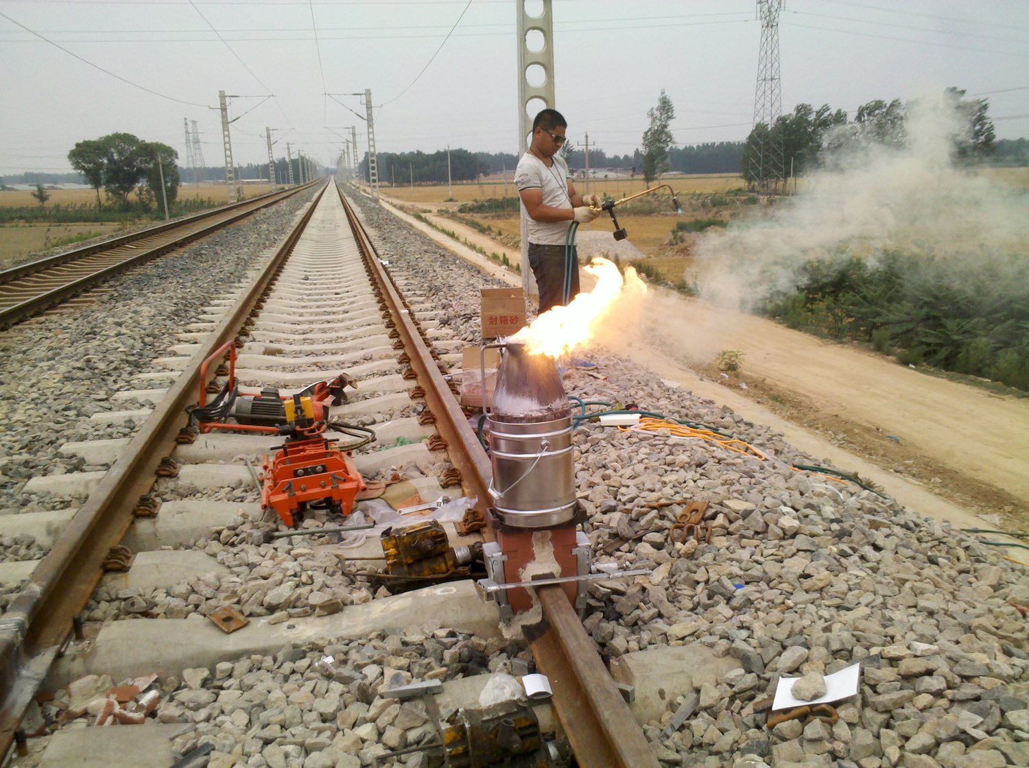
Why a Trunk Line Repair Turns Into a Railroad Thermite Welding Job
The Five-Stage Workflow of a Rail Welding Campaign
Stage 1 — Cutting Out the Defective Rail Section
Stage 2 — Installing and Aligning the Replacement Rail
Stage 3 — The Second Cut: Preparing the Closure Gap
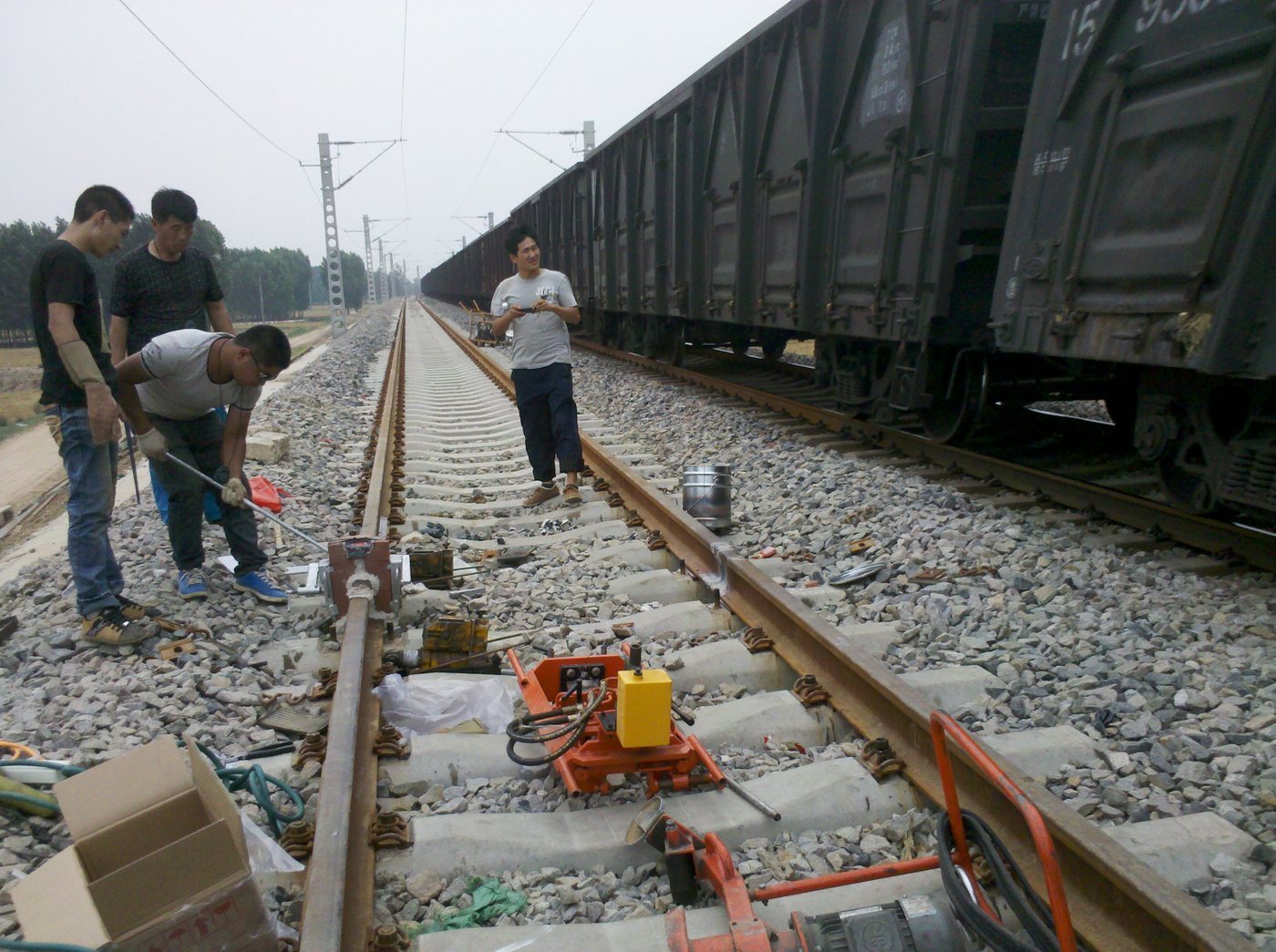
Stage 4 — The Railroad Thermite Welding Sequence
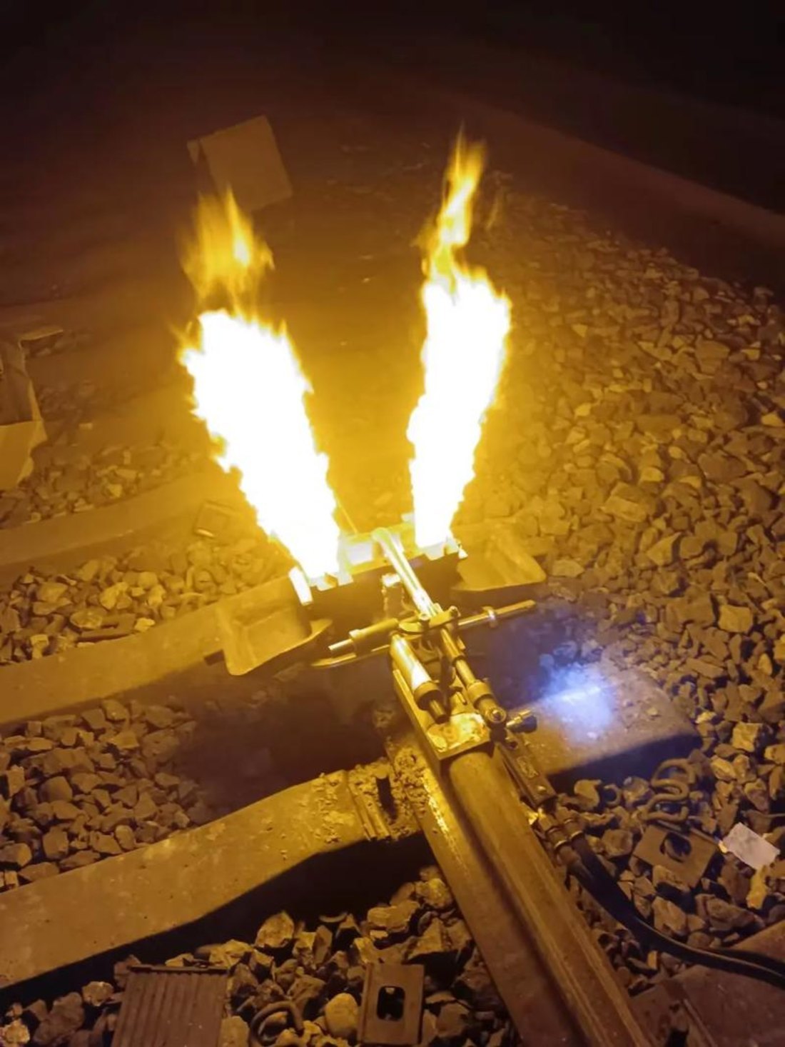
Stage 5 — Weld Inspection Before Track Handback
Acceptance, Handback and the Records That Stay Behind
Why the Job Used Two Different Cutting Tools
What Other Track Operators Can Take From This Work
Why is thermite welding still used when flash-butt welding is preferred?
Why is the rail cut a second time before the joint is poured?
When can ultrasonic testing be carried out on a new joint?
What happens if a joint fails inspection?
How long before trains can run over a newly welded joint?
Does a new joint need inspection again later?
Talk to RailwayCare
Are you looking for a reliable manufacturer of railway grinding and track maintenance equipment?
We can quickly provide customers with market analysis, technical support and customized services.
Safe Tracks Proven by China
- Name
- Phone
- *Title
- *Content